mbeva
mbeva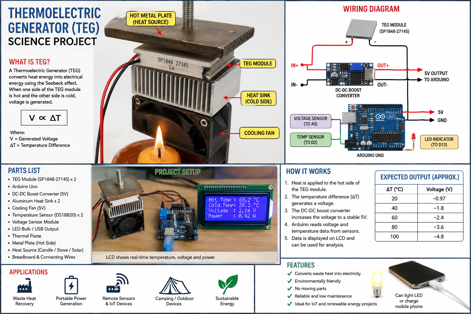
A thermoelectric generator converts heat directly into electricity using the Seebeck Effect. When one side of the TEG module is hot and the other side is cold, voltage is generated.
Basic Working Principle
V∝ΔT
Where:
- V = Generated Voltage
- ΔT = Temperature Difference between hot and cold sides
The larger the temperature difference, the higher the voltage output.
Required Parts List
Main Components
- Thermoelectric Generator Module
- SP1848-27145 Thermoelectric Generator Module
- Recommended: 2–4 modules for higher output
- Microcontroller
- Arduino Uno R4
- DC-DC Boost Converter
- Converts low TEG voltage to stable 5V
- Aluminum Heat Sink
- Cooling Fan (5V)
- Temperature Sensors
- DS18B20 or LM35
- LED Bulb or USB Output Port
- Thermal Paste
- Connecting Wires
- Breadboard
- Metal Plate (Hot Side)
- Heat Source
- Candle
- Charcoal stove
- Hot water container
- Solar concentrator
Estimated Cost (Kenya)
| Component | Quantity | Approx Cost (KSh) |
|---|---|---|
| TEG Module | 2 | 600–1,200 |
| Arduino Uno | 1 | 1,000–2,500 |
| Boost Converter | 1 | 150–300 |
| Heat Sink | 2 | 300–700 |
| Cooling Fan | 1 | 150–400 |
| Temperature Sensor | 2 | 200–400 |
| Breadboard & Wires | 1 | 300–600 |
Total: KSh 2,700 – 6,000
Full Wiring Diagram
                HOT METAL PLATE
                      ▲
                      │ Heat
                      │
        ┌────────────────────────┐
        │    TEG MODULE          │
        └────────────────────────┘
                      │
                      ▼
                HEAT SINK
                      │
                 COOLING FAN

              TEG OUTPUT
                 (+) (-)
                   │
                   ▼

         DC-DC BOOST CONVERTER

          IN+  ◄── TEG +
          IN-  ◄── TEG -

          OUT+ ──► 5V Arduino
          OUT- ──► GND Arduino

Arduino:
---------
5V   ◄──── Boost OUT+
GND  ◄──── Boost OUT-

A0   ◄──── Voltage Sensor

D2   ◄──── Temperature Sensor

D13  ────► LED Indicator
Arduino Code
int sensorPin = A0;

void setup() {
  Serial.begin(9600);
}

void loop() {

  int sensorValue = analogRead(sensorPin);

  float voltage =
  sensorValue * (5.0 / 1023.0);

  Serial.print("Generated Voltage: ");
  Serial.print(voltage);
  Serial.println(" V");

  delay(1000);
}
Assembly Procedure
Step 1
Apply thermal paste on both sides of the TEG module.
Step 2
Attach:
- Hot metal plate on one side
- Heat sink on the other side
Step 3
Mount cooling fan onto the heat sink.
Step 4
Connect TEG output wires to the boost converter.
Step 5
Set boost converter output to 5V.
Step 6
Connect boost converter to Arduino.
Step 7
Upload Arduino code.
Step 8
Apply heat source and observe voltage generation.
Expected Output
According to SP1848-27145 specifications:
| Temperature Difference | Voltage |
|---|---|
| 20°C | ~0.97V |
| 40°C | ~1.8V |
| 60°C | ~2.4V |
| 80°C | ~3.6V |
| 100°C | ~4.8V |
How to Make It KSEF-Level Competitive
Add:
1. IoT Monitoring
- Arduino + WiFi Module (ESP8266)
- Upload temperature and voltage data to cloud dashboard
2. LCD Display
Shows:
- Hot side temperature
- Cold side temperature
- Generated voltage
- Generated current
3. Automatic Cooling System
Fan speed changes according to temperature difference.
4. AI Prediction
Use Arduino + Machine Learning model to predict maximum power generation based on temperature.
5. Solar + TEG Hybrid System
Attach TEG behind a solar panel to harvest waste heat.
6. Mobile Phone Charging Port
Add USB output for practical demonstration.
Useful Component Sources
This project can be presented under Physics, Energy & Transport, Electrical Engineering, or Applied Technology categories in events such as the Kenya Science and Engineering Fair.