mbeva
mbeva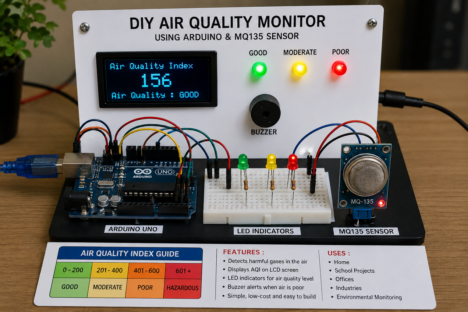


4
Introduction
This project involves building a simple device that monitors air quality using an Arduino Uno and an MQ135 gas sensor. The sensor detects harmful gases and pollutants in the air, while the Arduino processes the data and displays air quality levels using LEDs and a buzzer.
Materials Required
| Item | Quantity |
|---|---|
| Arduino Uno | 1 |
| MQ135 Air Quality Sensor | 1 |
| Breadboard | 1 |
| Jumper Wires | Several |
| Green LED | 1 |
| Yellow LED | 1 |
| Red LED | 1 |
| 220 Ω Resistors | 3 |
| Buzzer | 1 |
| USB Cable | 1 |
| Laptop with Arduino IDE | 1 |
Step 1: Understand How the Sensor Works
The MQ135 sensor contains a sensitive material that changes its electrical resistance when exposed to gases such as:
- Carbon dioxide (CO₂)
- Ammonia (NH₃)
- Benzene
- Smoke
- Alcohol vapours
The Arduino reads these changes and determines the air quality level.
Step 2: Assemble the Circuit
Connect the MQ135 Sensor
| MQ135 Pin | Arduino Pin |
|---|---|
| VCC | 5V |
| GND | GND |
| A0 | A0 |
Connect the LEDs
Green LED
- Positive leg → Pin 4 through 220 Ω resistor
- Negative leg → GND
Yellow LED
- Positive leg → Pin 5 through 220 Ω resistor
- Negative leg → GND
Red LED
- Positive leg → Pin 6 through 220 Ω resistor
- Negative leg → GND
Connect the Buzzer
| Buzzer Pin | Arduino Pin |
|---|---|
| Positive | Pin 7 |
| Negative | GND |
Step 3: Build the Circuit on the Breadboard
Arrange the components neatly:
- Place the Arduino beside the breadboard.
- Insert the MQ135 sensor on the breadboard.
- Place the three LEDs in a row.
- Connect all grounds to the breadboard ground rail.
- Use jumper wires to complete all connections.
Step 4: Install Arduino Software
- Download Arduino IDE.
- Install it on your computer.
- Connect the Arduino using the USB cable.
- Select:
- Board → Arduino Uno
- Port → COM Port of your Arduino
Step 5: Upload the Program
Copy and paste the following code into Arduino IDE.
int sensorPin = A0;
int greenLED = 4;
int yellowLED = 5;
int redLED = 6;
int buzzer = 7;

void setup()
{
  Serial.begin(9600);

  pinMode(greenLED, OUTPUT);
  pinMode(yellowLED, OUTPUT);
  pinMode(redLED, OUTPUT);
  pinMode(buzzer, OUTPUT);
}

void loop()
{
  int airValue = analogRead(sensorPin);

  Serial.print("Air Quality = ");
  Serial.println(airValue);

  if(airValue < 200)
  {
    digitalWrite(greenLED, HIGH);
    digitalWrite(yellowLED, LOW);
    digitalWrite(redLED, LOW);
    digitalWrite(buzzer, LOW);
  }

  else if(airValue < 400)
  {
    digitalWrite(greenLED, LOW);
    digitalWrite(yellowLED, HIGH);
    digitalWrite(redLED, LOW);
    digitalWrite(buzzer, LOW);
  }

  else
  {
    digitalWrite(greenLED, LOW);
    digitalWrite(yellowLED, LOW);
    digitalWrite(redLED, HIGH);
    digitalWrite(buzzer, HIGH);
  }

  delay(1000);
}
Click Verify and then Upload.
Step 6: Test the Device
After uploading:
Clean Air
- Green LED ON
- Yellow LED OFF
- Red LED OFF
- Buzzer OFF
Moderate Pollution
- Yellow LED ON
Heavy Pollution
- Red LED ON
- Buzzer sounds
Step 7: Conduct Experiments
Measure air quality in different locations:
| Location | Sensor Reading | Air Quality |
|---|---|---|
| Classroom | ||
| Laboratory | ||
| Kitchen | ||
| Roadside | ||
| Near Vehicle Exhaust |
Record observations and compare results.
Step 8: Prepare Your Science Fair Display
Include:
Title
Smart Air Quality Monitoring System Using Arduino and MQ135 Sensor
Sections
- Introduction
- Problem Statement
- Objectives
- Materials
- Methodology
- Circuit Diagram
- Results
- Discussion
- Conclusion
- Recommendations
Expected Results
| Reading | Interpretation |
|---|---|
| 0–200 | Good Air |
| 200–400 | Moderate Air |
| 400–600 | Poor Air |
| Above 600 | Dangerous Air |
Advanced KSEF Upgrades
To make the project more competitive:
- Add an OLED display showing AQI.
- Add a DHT22 sensor for temperature and humidity.
- Use an ESP8266 Wi-Fi module to send data online.
- Create a mobile phone monitoring app.
- Power the system using a solar panel.
- Store data on an SD card for long-term analysis.
- Use AI to predict pollution trends.
Science Behind the Project
The MQ135 sensor converts chemical changes caused by pollutants into electrical signals. The Arduino interprets these signals and provides a real-time indication of air quality, helping people identify polluted environments and take appropriate action.
This project combines Environmental Science, Electronics, Programming, Data Analysis, and Public Health, making it an excellent science fair project for secondary school and KSEF competitions