mbeva
mbeva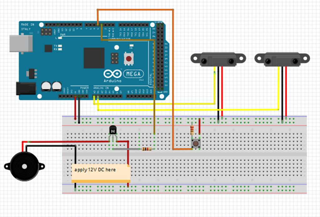
How to Make an Automated Electric Anti-Theft System
Project Title
Design and Construction of an Automated Electric Anti-Theft Security System Using Arduino and Motion Sensors
Project Images


System Components
Main Hardware Used in the Project


Working Principle of the System
Motion Detection → Processing → Alarm → SMS Alert


Security Light Activation
Automatic Illumination During Intrusion


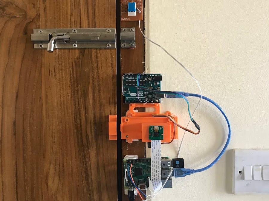
Construction and Assembly
Building the Automated Anti-Theft System


Applications of the Project
Where the System Can Be Used


Future Improvements
Advanced Smart Security Features


Operational Flow Diagram (Insert in Report)
System Powered ON
        │
        ▼
Monitor PIR Sensor
        │
        ▼
Motion Detected?
   ┌────┴────┐
   │         │
  NO        YES
   │         │
Continue   Activate Alarm
Monitoring     │
               ▼
        Turn ON Security Light
               │
               ▼
          Send SMS Alert
               │
               ▼
         Continue Monitoring
Introduction
The Automated Electric Anti-Theft System is a smart security device that detects unauthorized entry and automatically activates an alarm, lights, and notification system. The project can be used in homes, schools, shops, offices, and farms to prevent theft.
Objectives
- To detect unauthorized movement automatically.
- To trigger an alarm when intrusion occurs.
- To activate security lights automatically.
- To send notifications to the owner.
- To improve security using affordable technology.
Materials Required
| Item | Quantity |
|---|---|
| Arduino Uno | 1 |
| PIR Motion Sensor | 1 |
| Buzzer/Siren | 1 |
| Relay Module | 1 |
| LED Security Light | 1 |
| GSM Module (SIM800L) | 1 |
| Jumper Wires | Several |
| Breadboard | 1 |
| 12V Power Supply | 1 |
| Switch | 1 |
| Resistors | 2 |
| SIM Card | 1 |
System Components


6
Working Components
- PIR Sensor – Detects human movement.
- Arduino – Processes signals from sensors.
- Relay – Switches security lights ON.
- Buzzer – Produces alarm sound.
- GSM Module – Sends SMS alerts.
- LED Light – Illuminates the area.
Circuit Diagram
PIR Sensor
    │
    ▼
Arduino Uno
 ├──► Buzzer
 ├──► Relay ─► Security Light
 └──► GSM Module ─► SMS Alert
Construction Procedure
Step 1: Connect the PIR Sensor
- VCC → 5V Arduino
- GND → GND Arduino
- OUT → Digital Pin 2
Step 2: Connect Buzzer
- Positive terminal → Pin 8
- Negative terminal → GND
Step 3: Connect Relay Module
- IN → Pin 7
- VCC → 5V
- GND → GND
Step 4: Connect GSM Module
- TX → Arduino RX
- RX → Arduino TX
- Connect SIM card
Step 5: Upload Arduino Program
Program Arduino to:
- Monitor PIR sensor.
- Trigger buzzer when motion is detected.
- Switch ON security lights.
- Send SMS alert.
Operational Flow Chart
System Powered ON
        │
        ▼
Monitor PIR Sensor
        │
        ▼
Motion Detected?
   ┌────┴────┐
   │         │
  NO        YES
   │         │
Continue   Activate Alarm
Monitoring     │
               ▼
        Turn ON Security Light
               │
               ▼
          Send SMS Alert
               │
               ▼
         Continue Monitoring
Sample Arduino Code
int pir = 2;
int buzzer = 8;
int relay = 7;

void setup() {
pinMode(pir, INPUT);
pinMode(buzzer, OUTPUT);
pinMode(relay, OUTPUT);
}

void loop() {

if(digitalRead(pir)==HIGH){

digitalWrite(buzzer,HIGH);
digitalWrite(relay,HIGH);

delay(5000);

digitalWrite(buzzer,LOW);
digitalWrite(relay,LOW);
}

}
Testing Procedure
| Test | Expected Result |
|---|---|
| No movement | System remains idle |
| Motion detected | Alarm sounds |
| Motion detected | Light turns ON |
| GSM connected | SMS sent |
Expected Results
- Intruders detected automatically.
- Alarm activates immediately.
- Security lights illuminate the area.
- Owner receives warning message.
- Reduced theft incidents.
Possible Improvements
- Add fingerprint authentication.
- Add face recognition camera.
- Integrate with mobile application.
- Add solar charging system.
- Store intrusion records in cloud database.
- Use AI to distinguish humans from animals.
Applications
- Homes
- Schools
- Shops
- Warehouses
- Farms
- Offices
- Laboratories
Conclusion
The Automated Electric Anti-Theft System provides a reliable, low-cost, and intelligent method of protecting property from unauthorized access. By combining motion detection, alarms, lighting, and GSM communication, the system enhances security while reducing the need for continuous human monitoring.