mbeva
Design and Evaluation of an Arduino-Based Driver Alcohol Detection and Ignition Interlock Prototype.


8
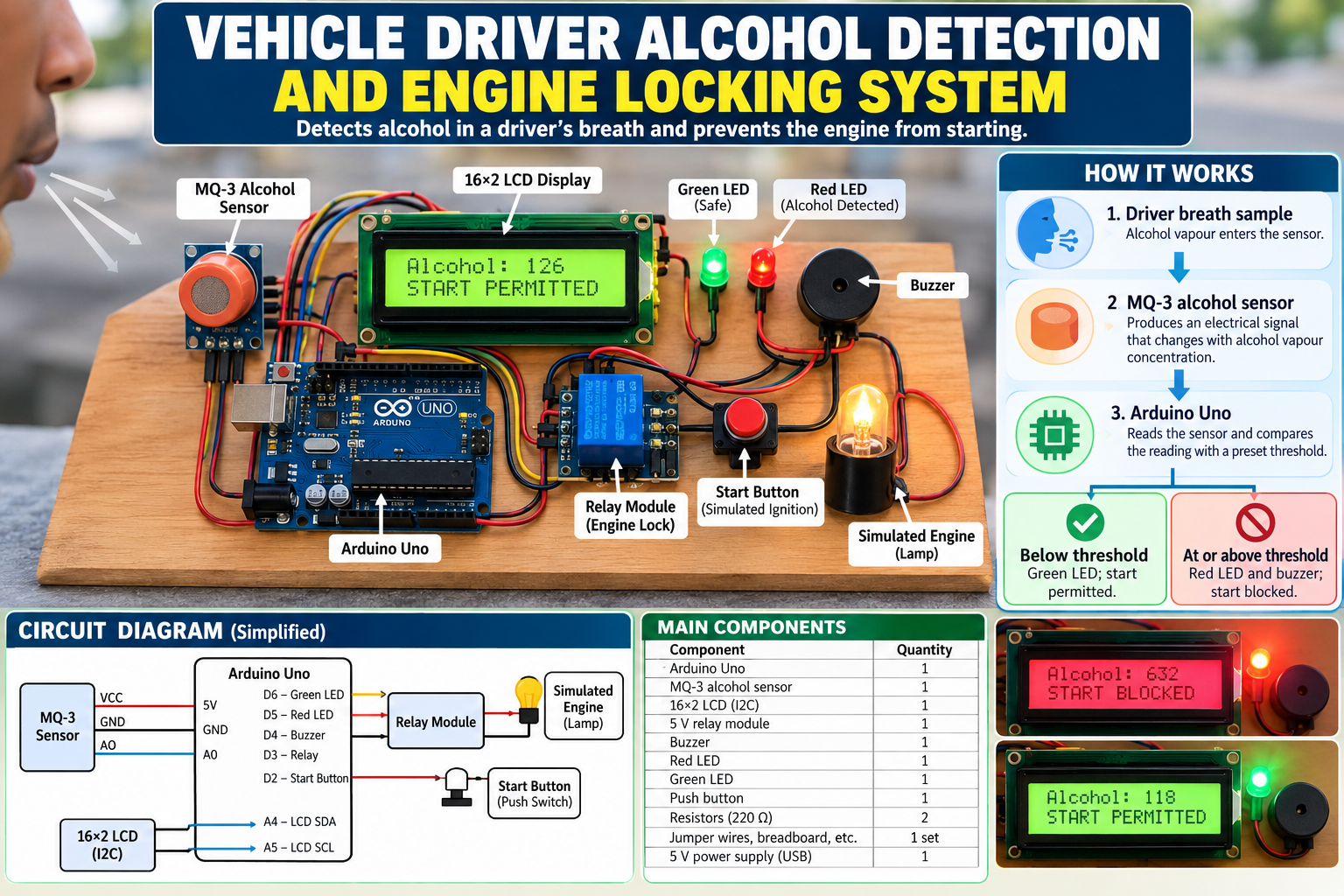
A Vehicle Driver Alcohol Detection and Engine Locking System is a road-safety engineering project designed to detect alcohol in a driver’s breath before a vehicle is started. If the sensor detects alcohol above a preset threshold, the system prevents the engine-start command and activates an alarm.
The project can be developed as a STEM innovation, science fair entry, or Kenya Science and Engineering Fair (KSEF) project using an Arduino, an MQ-3 alcohol sensor, a display, a buzzer and a relay-based demonstration circuit.
The recommended prototype uses a low-voltage simulated ignition system, rather than directly interrupting a real vehicle’s wiring. This makes it safer to build, test and demonstrate while preserving the main engineering principle.
1. How the system works
1. Driver breath sample
Alcohol vapour enters the sensor area.
2. MQ-3 alcohol sensor
Produces an electrical signal that changes with alcohol vapour concentration.
3. Arduino Uno
Reads the sensor and compares the reading with a calibrated threshold.
Below threshold
Green LED; simulated start permitted.
At or above threshold
Red LED and buzzer; simulated start blocked.
Important: The MQ-3 is a low-cost demonstration sensor, not a certified evidential breathalyser. Its readings are affected by calibration, temperature, humidity, warm-up time and other vapours. A prototype reading must not be treated as proof that a person is legally fit or unfit to drive.
2. Materials and components required


6
The following components are suitable for a school-level prototype.
| Component | Quantity | Purpose |
|---|---|---|
| Arduino Uno | 1 | Processes sensor readings |
| MQ-3 alcohol sensor module | 1 | Detects alcohol vapour |
| 16×2 LCD with I2C interface | 1 | Displays system status |
| 5 V relay module | 1 | Controls a simulated ignition circuit |
| Active buzzer | 1 | Provides an audible warning |
| Red LED | 1 | Indicates a detected-alcohol condition |
| Green LED | 1 | Indicates a permitted simulated start |
| 220 Ω resistors | 2 | Limit LED current |
| Push button | 1 | Simulates the engine-start request |
| 5 V USB power supply | 1 | Powers the prototype |
| Breadboard and jumper wires | 1 set | Makes electrical connections |
| Low-voltage lamp or LED load | 1 | Demonstrates the simulated ignition output |
An MQ-3 module typically provides an analogue output and may also provide a digital threshold output. Its heater requires a suitable supply, and the sensor can become hot during operation. Check the specific module’s pin labels and specifications before connecting it.
UNIVERSAL-SOLDER Electronics
+1
3. System circuit diagram
The following is the logical wiring layout for the educational prototype. The relay switches only a low-voltage demonstration load.
MQ-3 alcohol sensor
VCC → 5 V · GND → GND · AO → A0
Arduino Uno
A0: sensor · D2: start button · D3: relay · D4: buzzer
D5: red LED · D6: green LED · A4/A5: I2C display
LCD display
Shows sensor reading and system status.
Alarm and LEDs
Provide audible and visual warnings.
Relay → low-voltage simulated ignition
Permits or blocks power to a lamp or other safe demonstration load.
4. Pin connection table
| Component pin | Arduino connection |
|---|---|
| MQ-3 VCC | 5 V |
| MQ-3 GND | GND |
| MQ-3 AO | A0 |
| Relay IN | D3 |
| Relay VCC and GND | Appropriate supply and common ground, as specified by the module |
| Buzzer positive | D4, if compatible with the pin’s current rating |
| Buzzer negative | GND |
| Red LED anode | D5 through a 220 Ω resistor |
| Green LED anode | D6 through a 220 Ω resistor |
| LED cathodes | GND |
| Start button | D2 and GND |
| LCD SDA | A4 |
| LCD SCL | A5 |
| LCD VCC and GND | Supply and GND according to the display module |
Relay safety: Verify whether your relay module is active-high or active-low before testing. Some modules energise the relay when the control pin is LOW. The demonstration circuit must be wired so a reset, disconnected sensor or unpowered Arduino cannot accidentally indicate that a vehicle is safe to start.
For a real vehicle, do not connect this hobby circuit directly to the starter, ignition, fuel pump or vehicle control unit. A production interlock requires automotive-rated hardware, a fail-safe design and qualified installation.
5. How to assemble the system

Step 1: Connect the alcohol sensor
Connect VCC to 5 V, GND to GND and AO to analogue input A0. Allow the sensor to warm up and stabilise according to its datasheet before collecting readings.

Step 2: Install the display
Connect SDA to A4 and SCL to A5 on the Uno. The display will show the sensor reading and whether the simulated start is permitted or blocked.

Step 3: Connect the warning indicators
Connect the red and green LEDs through current-limiting resistors. Connect a suitable buzzer and relay module to the assigned pins.

Step 4: Build the simulated ignition
Use the relay to control a low-voltage lamp or LED load. Add the push button to represent a driver’s request to start the vehicle.
6. Arduino program
The program below implements the basic decision logic. The threshold is an illustrative sensor reading, not a blood-alcohol concentration or legal driving limit. Determine the appropriate value experimentally for the demonstration hardware.
This version uses the Arduino’s built-in LiquidCrystal library only if you use a parallel LCD; for the I2C LCD configuration described above, install a compatible LiquidCrystal_I2C library in the Arduino IDE.
#include <Wire.h>
#include <LiquidCrystal_I2C.h>

LiquidCrystal_I2C lcd(0x27, 16, 2);

// Pin assignments
const int alcoholPin = A0;
const int startButton = 2;
const int relayPin = 3;
const int buzzerPin = 4;
const int redLED = 5;
const int greenLED = 6;

// Illustrative only: calibrate for the specific sensor.
const int alcoholThreshold = 400;

// Set according to the relay module's behaviour.
const int RELAY_ON = LOW;
const int RELAY_OFF = HIGH;

bool startPermitted = false;

void setup() {
  pinMode(startButton, INPUT_PULLUP);
  pinMode(relayPin, OUTPUT);
  pinMode(buzzerPin, OUTPUT);
  pinMode(redLED, OUTPUT);
  pinMode(greenLED, OUTPUT);

  // Begin in the safe, blocked state.
  digitalWrite(relayPin, RELAY_OFF);
  digitalWrite(buzzerPin, LOW);
  digitalWrite(redLED, LOW);
  digitalWrite(greenLED, LOW);

  lcd.init();
  lcd.backlight();
  lcd.setCursor(0, 0);
  lcd.print("Alcohol Interlock");
  lcd.setCursor(0, 1);
  lcd.print("Sensor warming");
  delay(2000);
}

void loop() {
  int reading = analogRead(alcoholPin);

  // A high reading is treated as a warning for
  // this prototype; verify direction during calibration.
  bool alcoholDetected = reading >= alcoholThreshold;
  bool buttonPressed = digitalRead(startButton) == LOW;

  // Fail-safe for this demonstration:
  // do not permit start when alcohol is detected.
  startPermitted = !alcoholDetected && buttonPressed;

  if (alcoholDetected) {
    digitalWrite(relayPin, RELAY_OFF);
    digitalWrite(redLED, HIGH);
    digitalWrite(greenLED, LOW);
    digitalWrite(buzzerPin, HIGH);
  } else {
    digitalWrite(redLED, LOW);
    digitalWrite(buzzerPin, LOW);

    if (buttonPressed) {
      digitalWrite(relayPin, RELAY_ON);
      digitalWrite(greenLED, HIGH);
    } else {
      digitalWrite(relayPin, RELAY_OFF);
      digitalWrite(greenLED, LOW);
    }
  }

  lcd.setCursor(0, 0);
  lcd.print("Sensor: ");
  lcd.print(reading);
  lcd.print("    ");

  lcd.setCursor(0, 1);
  if (alcoholDetected) {
    lcd.print("START BLOCKED   ");
  } else if (buttonPressed) {
    lcd.print("START PERMITTED ");
  } else {
    lcd.print("Press START     ");
  }

  delay(200);
}
Before uploading: Check the I2C LCD address, which is commonly 0x27 or 0x3F, and verify your relay’s trigger polarity. This example assumes that a higher analogue reading corresponds to greater alcohol response; some modules and circuit configurations may behave differently.
The code is for a bench prototype, not a safety-certified vehicle interlock. It also does not independently verify that a valid breath sample was supplied, distinguish alcohol from interfering substances, or provide tamper resistance.
7. Testing and evaluation
Test the prototype using controlled, repeatable conditions. Do not use alcohol consumption as a test method involving a driver who may operate a vehicle.
| Test | Expected result | Pass criterion |
|---|---|---|
| Power on | System initialises | Display operates |
| Clean-air baseline | Reading is recorded | Stable baseline after warm-up |
| Sensor response test | Reading changes when safely exposed to a controlled test vapour | Sensor response is measurable |
| Start button pressed below the demonstration threshold | Relay permits the simulated start | Lamp turns on |
| Start button pressed above the threshold | Relay blocks the simulated start | Lamp remains off |
| Alcohol warning condition | Red LED and buzzer activate | Both indicators operate |
| Arduino reset or power loss | System returns to a blocked state | Simulated start remains disabled |
| Sensor disconnected | System identifies a fault or remains blocked | No false permission to start |
The sensor’s response and recovery times vary by module and operating conditions. MQ-3 devices require warm-up and calibration, so record the baseline and repeated readings rather than assuming that a single reading proves accurate alcohol measurement.
Seeed Studio Wiki
+1
8. How to Fix Common Arduino Upload Errors
| Error | Possible cause | Solution |
|---|---|---|
avrdude: ser_open() | Incorrect port or unavailable serial port | Select the correct COM port and close other programs using it |
avrdude: stk500_recv() | Board or bootloader communication problem | Check the USB cable, board selection and connection |
LiquidCrystal_I2C.h: No such file | Missing display library | Install a compatible I2C LCD library |
| LCD lights up but shows no text | Incorrect I2C address or contrast | Check the address and adjust the contrast |
| Sensor readings remain constant | Wiring, sensor warm-up or faulty module | Check AO-to-A0 wiring and inspect the sensor response |
| Relay works in reverse | Active-low relay logic | Adjust RELAY_ON and RELAY_OFF |
| Relay activates during reset | Module input behaviour or unsafe default state | Rework the driver circuit and verify the default blocked condition |
9. Improving the project for KSEF


9
To improve the project’s scientific value, consider these extensions:
- Sensor calibration: Compare repeated sensor readings against a suitable calibrated reference instrument in a supervised laboratory.
- Data logging: Record sensor readings, response times, false alarms and successful start-blocking tests.
- Fault detection: Add sensor-disconnection detection, startup self-tests and a fail-safe state.
- Driver verification: Investigate methods of ensuring that the person providing the sample is the driver, without compromising privacy.
- Post-start monitoring: Research the requirements for safe repeat testing without abruptly disabling a moving vehicle.
- Improved sensing: Investigate fuel-cell-based breath alcohol measurement technology, which is used in professional interlock devices.
NHTSA+1
For a KSEF report, measure the system’s detection response, false-positive rate, false-negative rate and reliability over repeated trials. State the limitations of the sensor honestly and distinguish experimental sensor readings from actual breath-alcohol concentration.
10. Estimated project budget in Kenya
These are preliminary planning allowances, not verified current supplier quotations.
| Item | Estimated cost (KES) |
|---|---|
| Arduino Uno-compatible board | 800–1,500 |
| MQ-3 alcohol sensor | 250–600 |
| I2C LCD | 350–700 |
| Relay module | 150–350 |
| LEDs, resistors, buzzer and button | 150–350 |
| Breadboard and jumper wires | 300–600 |
| USB power supply and cable | 300–600 |
| Enclosure and demonstration load | 300–800 |
| Estimated total | 2,600–5,500 |
The final cost depends on the components already available in the school laboratory and the quality of the enclosure and power supply.
11. Conclusion
The Vehicle Driver Alcohol Detection and Engine Locking System demonstrates how gas sensing, microcontroller programming, electronic switching and warning indicators can be combined to address road safety. A successful school prototype should detect a sensor response, display its status, activate an alarm and block a simulated engine-start request when the preset demonstration threshold is reached.
A real vehicle installation is a separate engineering task. Certified alcohol interlocks have requirements beyond basic sensor detection, including breath-sample validation, reliable operation and safe integration with the vehicle.