mbeva
mbeva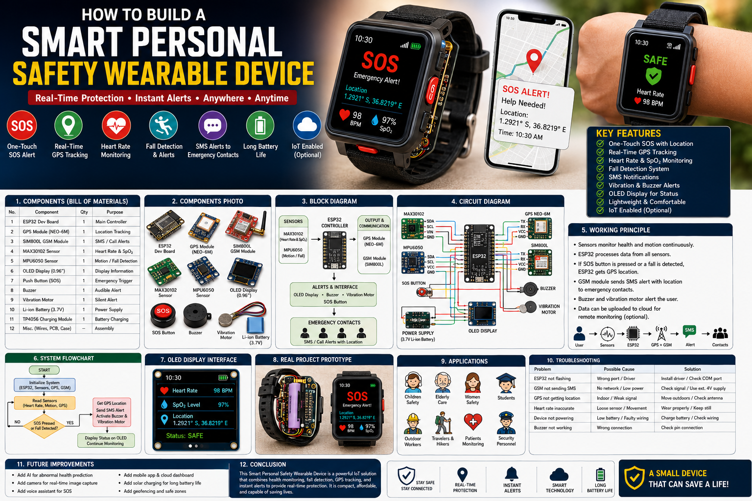
Meta Title: How to Build a Smart Personal Safety Wearable Device Using ESP32 and GSM
Meta Description: Learn how to build a Smart Personal Safety Wearable Device using ESP32, GPS, GSM, pulse sensors, and emergency SOS systems. Includes wiring diagrams, bill of materials, circuit diagrams, working principles, flowcharts, troubleshooting tips, and realkl
Personal safety has become increasingly important for children, students, elderly individuals, travelers, and outdoor workers. A Smart Personal Safety Wearable Device provides real-time location tracking, emergency alerts, health monitoring, and automatic accident detection.
This project combines ESP32, GPS, GSM, IoT, and wearable electronics to create an intelligent safety device capable of protecting users in emergency situations.
Quick Answer: Smart Personal Safety Wearable Wiring Diagram
If you want to build the project immediately, use the following wiring configuration.
| Component | Pin | ESP32 Pin |
|---|---|---|
| MAX30102 Pulse Sensor | SDA | GPIO21 |
| MAX30102 Pulse Sensor | SCL | GPIO22 |
| GPS Module TX | TX | GPIO16 |
| GPS Module RX | RX | GPIO17 |
| SIM800L TX | TX | GPIO26 |
| SIM800L RX | RX | GPIO27 |
| Push Button SOS | Signal | GPIO4 |
| MPU6050 Accelerometer | SDA | GPIO21 |
| MPU6050 Accelerometer | SCL | GPIO22 |
| OLED Display | SDA | GPIO21 |
| OLED Display | SCL | GPIO22 |
| Buzzer | Positive | GPIO18 |
| Vibration Motor | Positive | GPIO19 |
Important: SIM800L requires an external 4V power supply due to high current demands during SMS transmission.
System Workflow
User → Wearable Sensors → ESP32 Processing → GPS Location → GSM Alert → Emergency Contacts


4
Why Build a Smart Personal Safety Wearable Device?
Many emergencies require immediate assistance.
This wearable device can help:
Benefits
- Emergency SOS notifications
- Real-time location tracking
- Fall detection
- Health monitoring
- Child and elderly protection
- Remote family monitoring
This project is ideal for smart healthcare and personal security applications.
How Does the Smart Safety Wearable Work?
The system consists of five major sections.
1. Health Monitoring
The MAX30102 sensor measures:
- Heart rate
- Blood oxygen levels
2. Motion Detection
The MPU6050 detects:
- Falls
- Sudden impacts
- Unusual movements
3. Location Tracking
GPS continuously monitors user location.
4. Emergency Communication
SIM800L sends:
- SMS alerts
- Emergency coordinates
- Phone notifications
5. User Interface
OLED display provides:
- Pulse information
- GPS status
- Battery level
- Emergency messages


6
Bill of Materials (BOM)
| Component | Quantity | Purpose |
|---|---|---|
| ESP32 Development Board | 1 | Main controller |
| MAX30102 Sensor | 1 | Heart rate and SpO₂ monitoring |
| MPU6050 Accelerometer | 1 | Fall detection |
| GPS Module NEO-6M | 1 | Location tracking |
| SIM800L GSM Module | 1 | SMS alerts |
| OLED Display | 1 | Displays information |
| Push Button | 1 | SOS activation |
| Buzzer | 1 | Audible alerts |
| Vibration Motor | 1 | Silent alerts |
| Li-Ion Battery | 1 | Portable power |
| Charging Module TP4056 | 1 | Battery charging |
| Wrist Strap | 1 | Wearable enclosure |
Estimated Project Cost
| Item | Approximate Cost |
|---|---|
| ESP32 | $8 |
| GPS Module | $8 |
| GSM Module | $8 |
| MAX30102 | $5 |
| MPU6050 | $3 |
| Miscellaneous | $15 |
Estimated Total Cost: $45–60
Components Overview


4
Key Features
✅ Emergency SOS alerts
✅ GPS location tracking
✅ Heart rate monitoring
✅ Fall detection
✅ SMS notifications
✅ Silent vibration alerts
✅ Mobile dashboard integration
Block Diagram
Wearable Sensors
      ↓
ESP32 Controller
      ↓
GPS + GSM Modules
      ↓
OLED + Alerts
      ↓
Emergency Contacts


5
Circuit Connections Explained
MAX30102 Sensor
- SDA → GPIO21
- SCL → GPIO22
GPS Module
- TX → GPIO16
- RX → GPIO17
SIM800L Module
- TX → GPIO26
- RX → GPIO27
SOS Button
- Signal → GPIO4
Alerts
Buzzer → GPIO18
Vibration Motor → GPIO19


6
Step-by-Step Guide: How to Build a Smart Personal Safety Wearable Device
Step 1: Assemble Electronics
Connect all modules according to the wiring diagram.
Ensure proper battery management.
Step 2: Install Sensors
Attach:
- Pulse sensor
- Accelerometer
- GPS antenna
inside the wearable enclosure.
Step 3: Upload ESP32 Program
The program should:
- Read heart rate.
- Detect falls.
- Monitor GPS coordinates.
- Send alerts during emergencies.
Example logic:
IF SOS Button Pressed

Get GPS Location

Send SMS Alert

Activate Buzzer

ELSE IF Fall Detected

Automatically Send Alert
Step 4: Configure Emergency Contacts
Store:
- Parent phone numbers
- Guardians
- Emergency responders
inside the system.
Step 5: Test the Device
Verify:
- GPS tracking
- SOS button functionality
- Heart monitoring
- Fall detection


7
Working Principle
The wearable continuously monitors:
- User health.
- Body movements.
- GPS location.
During emergencies:
- ESP32 processes sensor data.
- GSM sends alerts.
- Emergency contacts receive coordinates.
This creates a real-time personal protection network.
Applications
This project can be used by:
- Children
- Elderly people
- Travelers
- Hikers
- Patients
- Students
- Security personnel
- Outdoor workers
Advantages and Limitations
Advantages
- Portable
- Real-time monitoring
- Immediate emergency response
- Low cost
- Expandable with AI
Limitations
- GPS requires open sky.
- GSM depends on network coverage.
- Battery life may be limited.
Future Improvements
You can improve the project by adding:
AI Emergency Prediction
Predict possible medical emergencies.
Voice Recognition
Activate SOS through voice commands.
Camera Integration
Capture images during emergencies.
Cloud Dashboard
Monitor multiple users remotely.
Solar Charging
Increase battery life.
How to Fix Common ESP32 Upload Errors
Error: Failed Connecting to ESP32
Solutions
- Hold BOOT button during upload.
- Install drivers.
- Check COM port.
Error: GPS Cannot Obtain Coordinates
Solutions
- Move outdoors.
- Check antenna orientation.
Error: GSM Cannot Send SMS
Solutions
- Verify SIM card activation.
- Use external power supply.
- Check network signal.
Error: Pulse Sensor Gives Incorrect Readings
Solutions
- Ensure proper skin contact.
- Reduce movement noise.


6
Featured Images Required for Blog
1. Components Image
- ESP32
- GPS Module
- GSM Module
- Pulse Sensor
- Accelerometer
2. Features Illustration
- SOS alerts
- GPS tracking
- Health monitoring
- Fall detection
3. Block Diagram
- Sensors → ESP32 → GSM → Emergency Contacts
4. Working Principle Diagram
- User → Sensor → Processing → Alert
5. Circuit Diagram
- Complete wearable wiring layout
6. Flowchart
- Emergency detection process
7. Real Prototype Photo
- Fully assembled smart wearable device
Final Thoughts
Learning how to build a Smart Personal Safety Wearable Device is one of the most practical ESP32 and IoT projects.
By combining GPS tracking, GSM alerts, health monitoring, and fall detection, you can create an intelligent wearable capable of protecting users during emergencies.