mbeva
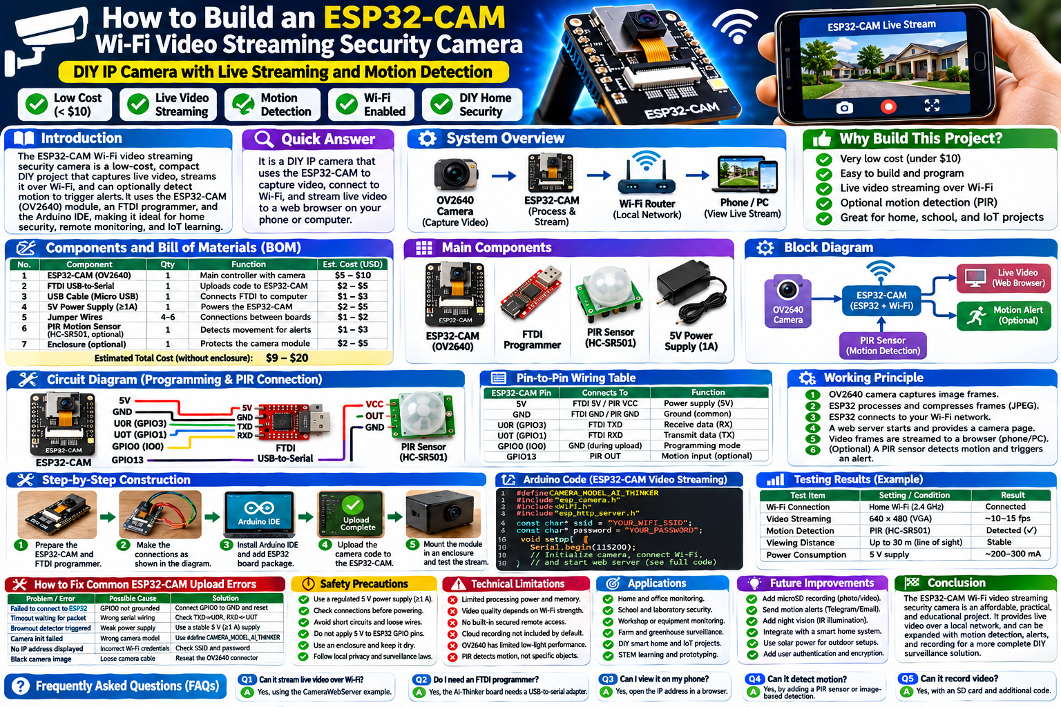
How to Build an ESP32-CAM Wi-Fi Video Streaming Security Camera
This is the complete project article again, covering the AI-Thinker ESP32-CAM with OV2640 camera, Arduino IDE programming, FTDI wiring, live Wi-Fi streaming, optional PIR motion detection, testing, and troubleshooting.
. Introduction: Why Build an ESP32-CAM Security Camera?
Home security and remote monitoring are increasingly important in homes, schools, workshops, laboratories, farms, and small businesses. Commercial IP cameras provide convenient monitoring, but they may be unnecessarily expensive for learners and electronics hobbyists who want to understand how wireless surveillance works.
The ESP32-CAM Wi-Fi video streaming security camera is a compact, low-cost Internet of Things (IoT) project. It combines an ESP32 microcontroller, an OV2640 camera module, and built-in Wi-Fi connectivity to capture images and stream live video to a web browser.
The project is particularly useful for STEM learners, Arduino enthusiasts, electronics students, and developers exploring embedded systems, wireless communication, and computer vision.
What the project can do
- Capture images using the OV2640 camera.
- Connect to a local Wi-Fi network.
- Host a camera interface on a web server.
- Stream live video to a phone or computer.
- Support optional PIR motion detection.
- Provide a foundation for image recording and notification upgrades.
Important distinction: The basic project provides local video streaming. Motion alerts, cloud recording, and secure remote access require additional hardware or software.
. Quick Answer: How Does ESP32-CAM Video Streaming Work?
The OV2640 camera captures image frames. The ESP32 processes the frames, compresses them into JPEG images, and sends them over a local Wi-Fi network through an HTTP streaming server.
A phone or computer connected to the same network opens the camera’s IP address and displays the live stream.
ESP32-CAM system overview
OV2640 Camera Sensor
Captures image frames
ESP32-CAM Microcontroller
Processes frames and manages Wi-Fi
Wi-Fi Router
Provides local network communication
Computer
Web browser
Smartphone
Web browser
5. Components and Bill of Materials (BOM)
How to Program / Upload Code to ESP32-CAM AI-Thinker (Arduino IDE) | Random Nerd Tutorials
The project can be assembled using a small number of components. The common AI-Thinker ESP32-CAM board usually comes with an OV2640 camera module.
| Component | Quantity | Function | Indicative cost (USD) |
|---|---|---|---|
| AI-Thinker ESP32-CAM | 1 | Main controller and camera board | $5–$10 |
| OV2640 camera | 1 | Captures images | Usually included |
| FTDI USB-to-serial adapter | 1 | Programs the board | $2–$5 |
| USB cable | 1 | Connects programmer to computer | $1–$3 |
| Regulated 5 V supply | 1 | Powers the camera | $2–$5 |
| Jumper wires | 4–6 | Electrical connections | $1–$2 |
| Breadboard | 1 optional | Prototyping | Varies |
| Enclosure | 1 optional | Protects electronics | $2–$5 |
| HC-SR501 PIR sensor | 1 optional | Detects movement | $1–$3 |
Prices are illustrative estimates, not live supplier quotations. Local prices and shipping costs vary.
Understanding the main components
Ai-Thinker ESP32-CAM WiFi BT BLE Ai-Thinker | Sensor Evaluation Boards | DigiKey Marketplace
ESP32-CAM board
Contains the ESP32 microcontroller, Wi-Fi, camera interface, and commonly a microSD card slot.
Jual BEST NEW OV2640 Camera Module for ESP32 CAM Camera Module 120 Degree | Shopee Indonesia
OV2640 camera
Captures image frames and provides JPEG image data to the ESP32.
FT232RL USB zu TTL Serial Adapter für 3,3V und 5V
FTDI programmer
Provides USB-to-serial communication for uploading firmware from the computer.
PIR Sensor HC-SR501 HC SR501 PIR Human Motion Infrared Detector Sensor Module | Daraz.pk
Optional PIR sensor
Detects changes in infrared radiation associated with movement.
6. Working Principle
ESP32-S3 N16R8 + OV5640: Tạo Streaming Camera xem trực tiếp trên trình duyệt – IoTLabs Maker
The system operates through six main stages:
- Image capture: The OV2640 captures an image frame.
- Image processing: The ESP32 receives the frame and handles the JPEG data.
- Wireless connection: The ESP32 joins the configured Wi-Fi network.
- Web server initialization: The board starts an HTTP server.
- Video streaming: The server sends a continuous sequence of JPEG frames using an MJPEG stream.
- Browser display: A phone or computer displays the stream through a browser.
System block diagram
Functional block diagram
OV2640 Camera Sensor
Image capture
ESP32-CAM Controller
Image processing and JPEG frames
Wi-Fi and HTTP Server
MJPEG video stream
Local Wi-Fi Network
Computer browser
Phone browser
Optional PIR sensor → Motion event
Additional input for motion detection
7. ESP32-CAM Circuit Diagram and FTDI Connections
The common AI-Thinker ESP32-CAM board does not have a built-in USB programming connector. An FTDI USB-to-serial adapter is commonly used to upload the Arduino program.
ESP32-CAM Beginner’s Guide. The ESP32-CAM is an amazing small… | by Jahja Trifunovic | Medium
Pin-to-pin wiring table
| ESP32-CAM pin | FTDI pin | Function |
|---|---|---|
| 5V | 5V | Power input |
| GND | GND | Common ground |
| U0R / GPIO3 | TXD | Serial receive |
| U0T / GPIO1 | RXD | Serial transmit |
| GPIO0 | GND | Programming mode during upload |
The serial data connections must cross: FTDI TXD connects to ESP32-CAM U0R, and FTDI RXD connects to ESP32-CAM U0T.
Programming connection schematic
       FTDI USB-TO-SERIAL                 ESP32-CAM

       5V  ------------------------------ 5V
       GND ------------------------------ GND
       TXD ------------------------------ U0R (GPIO3)
       RXD ------------------------------ U0T (GPIO1)

                                           GPIO0
                                             |
                                             |
                                            GND
                                     (UPLOAD MODE ONLY)
ESP32-CAM not flashable with ESPHome? – ESPHome – Home Assistant Community
Power supply requirements
- Use a regulated 5 V supply with sufficient current capacity. A 1 A-rated supply is a reasonable starting point.
- Some FTDI adapters cannot reliably power the camera during Wi-Fi transmission.
- Check the FTDI voltage selection before connecting it.
- Never apply 5 V directly to an ESP32 GPIO pin.
- Disconnect GPIO0 from GND after uploading the firmware.
8. Installing Arduino IDE and ESP32 Board Support
Step 1: Install Arduino IDE
Download the software from the official Arduino IDE download page.
Step 2: Add the ESP32 board package
Open File → Preferences and add this URL to Additional Boards Manager URLs:
https://espressif.github.io/arduino-esp32/package_esp32_index.jsonNext:
- Open Tools → Board → Boards Manager.
- Search for
esp32. - Install the package published by Espressif Systems.
Step 3: Select the AI-Thinker ESP32-CAM
Select the matching ESP32-CAM board definition in the Arduino IDE. The exact board menu options can vary by ESP32 Arduino core version.
The CameraWebServer example supplied with Espressif’s package is a recommended starting point.
9. Complete Arduino Source Code for ESP32-CAM Video Streaming
The following is a compact standalone MJPEG streaming implementation for the common AI-Thinker ESP32-CAM board. It uses the ESP32 camera driver and HTTP server supplied with the Espressif Arduino core.
It provides:
- Camera initialization.
- Wi-Fi connection.
- A simple home page.
- Live MJPEG streaming at
/stream. - A camera snapshot at
/capture.
It does not include cloud access, authentication, recording, or PIR notifications.
Arduino code
#include "esp_camera.h"
#include <WiFi.h>
#include "esp_http_server.h"

// -------------------------------
// Wi-Fi credentials
// -------------------------------
const char* ssid = "YOUR_WIFI_NAME";
const char* password = "YOUR_WIFI_PASSWORD";

// -------------------------------
// AI-Thinker ESP32-CAM pin mapping
// -------------------------------
#define PWDN_GPIO_NUM     32
#define RESET_GPIO_NUM    -1
#define XCLK_GPIO_NUM      0
#define SIOD_GPIO_NUM     26
#define SIOC_GPIO_NUM     27

#define Y9_GPIO_NUM       35
#define Y8_GPIO_NUM       34
#define Y7_GPIO_NUM       39
#define Y6_GPIO_NUM       36
#define Y5_GPIO_NUM       21
#define Y4_GPIO_NUM       19
#define Y3_GPIO_NUM       18
#define Y2_GPIO_NUM        5

#define VSYNC_GPIO_NUM    25
#define HREF_GPIO_NUM     23
#define PCLK_GPIO_NUM     22

httpd_handle_t camera_httpd = NULL;

static const char* STREAM_CONTENT_TYPE =
  "multipart/x-mixed-replace;boundary=frame";

static const char* STREAM_BOUNDARY =
  "\r\n--frame\r\n";

static const char* STREAM_PART =
  "Content-Type: image/jpeg\r\n"
  "Content-Length: %u\r\n\r\n";

// -------------------------------
// Camera configuration
// -------------------------------
bool startCamera() {
  camera_config_t config;

  config.ledc_channel = LEDC_CHANNEL_0;
  config.ledc_timer = LEDC_TIMER_0;

  config.pin_d0 = Y2_GPIO_NUM;
  config.pin_d1 = Y3_GPIO_NUM;
  config.pin_d2 = Y4_GPIO_NUM;
  config.pin_d3 = Y5_GPIO_NUM;
  config.pin_d4 = Y6_GPIO_NUM;
  config.pin_d5 = Y7_GPIO_NUM;
  config.pin_d6 = Y8_GPIO_NUM;
  config.pin_d7 = Y9_GPIO_NUM;

  config.pin_xclk = XCLK_GPIO_NUM;
  config.pin_pclk = PCLK_GPIO_NUM;
  config.pin_vsync = VSYNC_GPIO_NUM;
  config.pin_href = HREF_GPIO_NUM;

  config.pin_sccb_sda = SIOD_GPIO_NUM;
  config.pin_sccb_scl = SIOC_GPIO_NUM;

  config.pin_pwdn = PWDN_GPIO_NUM;
  config.pin_reset = RESET_GPIO_NUM;

  config.xclk_freq_hz = 20000000;
  config.pixel_format = PIXFORMAT_JPEG;

  if (psramFound()) {
    config.frame_size = FRAMESIZE_VGA;
    config.jpeg_quality = 12;
    config.fb_count = 2;
    config.grab_mode = CAMERA_GRAB_LATEST;
    config.fb_location = CAMERA_FB_IN_PSRAM;
  } else {
    config.frame_size = FRAMESIZE_QVGA;
    config.jpeg_quality = 15;
    config.fb_count = 1;
    config.grab_mode = CAMERA_GRAB_WHEN_EMPTY;
    config.fb_location = CAMERA_FB_IN_DRAM;
  }

  esp_err_t err = esp_camera_init(&config);

  if (err != ESP_OK) {
    Serial.printf("Camera initialization failed: 0x%x\n", err);
    return false;
  }

  return true;
}

// -------------------------------
// Main camera web page
// -------------------------------
static esp_err_t index_handler(
  httpd_req_t *req
) {
  const char* html =
    "<!DOCTYPE html><html><head>"
    "<meta name='viewport' "
    "content='width=device-width,initial-scale=1'>"
    "<title>ESP32-CAM Security Camera</title>"
    "<style>"
    "body{font-family:Arial;text-align:center;"
    "background:#eef2f7;margin:20px;}"
    "img{width:100%;max-width:640px;"
    "border-radius:10px;}"
    "</style></head><body>"
    "<h2>ESP32-CAM Live Camera</h2>"
    "<img src='/stream'>"
    "<p>Local Wi-Fi video streaming</p>"
    "</body></html>";

  httpd_resp_set_type(req, "text/html");
  return httpd_resp_send(req, html, HTTPD_RESP_USE_STRLEN);
}

// -------------------------------
// Single JPEG capture
// -------------------------------
static esp_err_t capture_handler(
  httpd_req_t *req
) {
  camera_fb_t *fb = esp_camera_fb_get();

  if (!fb) {
    httpd_resp_send_500(req);
    return ESP_FAIL;
  }

  httpd_resp_set_type(req, "image/jpeg");

  esp_err_t res = httpd_resp_send(
    req,
    (const char*)fb->buf,
    fb->len
  );

  esp_camera_fb_return(fb);
  return res;
}

// -------------------------------
// MJPEG streaming handler
// -------------------------------
static esp_err_t stream_handler(
  httpd_req_t *req
) {
  esp_err_t res = ESP_OK;

  res = httpd_resp_set_type(
    req,
    STREAM_CONTENT_TYPE
  );

  if (res != ESP_OK) return res;

  httpd_resp_set_hdr(
    req,
    "Access-Control-Allow-Origin",
    "*"
  );

  while (true) {
    camera_fb_t *fb = esp_camera_fb_get();

    if (!fb) {
      res = ESP_FAIL;
      break;
    }

    char part_buf[64];

    size_t hlen = snprintf(
      part_buf,
      sizeof(part_buf),
      STREAM_PART,
      fb->len
    );

    res = httpd_resp_send_chunk(
      req,
      STREAM_BOUNDARY,
      strlen(STREAM_BOUNDARY)
    );

    if (res == ESP_OK) {
      res = httpd_resp_send_chunk(
        req,
        part_buf,
        hlen
      );
    }

    if (res == ESP_OK) {
      res = httpd_resp_send_chunk(
        req,
        (const char*)fb->buf,
        fb->len
      );
    }

    esp_camera_fb_return(fb);

    if (res != ESP_OK) break;
  }

  return res;
}

// -------------------------------
// Start web server
// -------------------------------
void startCameraServer() {
  httpd_config_t config = HTTPD_DEFAULT_CONFIG();

  config.server_port = 80;
  config.ctrl_port = 32768;
  config.max_uri_handlers = 8;

  if (httpd_start(&camera_httpd, &config) == ESP_OK) {

    httpd_uri_t index_uri = {
      .uri = "/",
      .method = HTTP_GET,
      .handler = index_handler,
      .user_ctx = NULL
    };

    httpd_uri_t capture_uri = {
      .uri = "/capture",
      .method = HTTP_GET,
      .handler = capture_handler,
      .user_ctx = NULL
    };

    httpd_uri_t stream_uri = {
      .uri = "/stream",
      .method = HTTP_GET,
      .handler = stream_handler,
      .user_ctx = NULL
    };

    httpd_register_uri_handler(
      camera_httpd, &index_uri
    );

    httpd_register_uri_handler(
      camera_httpd, &capture_uri
    );

    httpd_register_uri_handler(
      camera_httpd, &stream_uri
    );
  }
}

// -------------------------------
// Setup
// -------------------------------
void setup() {
  Serial.begin(115200);
  Serial.println();

  if (!startCamera()) {
    Serial.println("Restarting after camera error.");
    delay(3000);
    ESP.restart();
  }

  WiFi.mode(WIFI_STA);
  WiFi.begin(ssid, password);

  Serial.print("Connecting to Wi-Fi");

  unsigned long startAttempt = millis();

  while (
    WiFi.status() != WL_CONNECTED &&
    millis() - startAttempt < 30000
  ) {
    delay(500);
    Serial.print(".");
  }

  if (WiFi.status() != WL_CONNECTED) {
    Serial.println("\nWi-Fi connection failed.");
    return;
  }

  Serial.println("\nWi-Fi connected.");
  Serial.print("Camera IP address: ");
  Serial.println(WiFi.localIP());

  startCameraServer();

  Serial.println("Camera server started.");
}

// -------------------------------
// Main loop
// -------------------------------
void loop() {
  delay(1000);
}
Code configuration and explanation
1. Wi-Fi credentials
Replace the placeholders with the actual network name and password:
const char* ssid = "YOUR_WIFI_NAME";
const char* password = "YOUR_WIFI_PASSWORD";
The example is intended for a compatible 2.4 GHz Wi-Fi network. The ESP32-CAM does not connect to a 5 GHz-only network.
2. Camera pin mapping
The pin definitions correspond to the common AI-Thinker ESP32-CAM layout. Other ESP32-CAM variants may use different camera pins.
3. Image resolution
The example uses VGA when PSRAM is available and QVGA otherwise. These settings can be changed to suit the available memory and network conditions.
4. HTTP routes
| URL path | Function |
|---|---|
/ | Camera viewing page |
/stream | Continuous MJPEG stream |
/capture | Single JPEG image |
5. Wi-Fi connection
The program waits up to 30 seconds for Wi-Fi. If it does not connect, it prints an error to the Serial Monitor. Check the credentials and network before restarting.
Compatibility note: This sketch is written for the Espressif Arduino-ESP32 core with the current camera configuration structure and ESP-IDF HTTP server headers. If your installed core reports a camera configuration field error, check the installed core version and its CameraWebServer example. It has not been physically tested on your particular board, power supply, or camera module.
10. Step-by-Step Construction Guide
Elegoo Smart Robot Car V4 cannot upload ESP32-camera code – IDE 1.x – Arduino Forum
Step 1: Prepare the ESP32-CAM
Inspect the board and confirm that the OV2640 camera is correctly connected.
ESP32 CAM WEB Server and Getting Started Guide : 6 Steps (with Pictures) – Instructables
Check that the camera ribbon cable is seated correctly and that its contacts align with the connector. Handle the ribbon carefully because it can be damaged by excessive force.
Step 2: Connect the FTDI programmer
How to Program / Upload Code to ESP32-CAM AI-Thinker (Arduino IDE) | Random Nerd Tutorials
Connect the FTDI adapter according to the wiring table:
- 5V to 5V.
- GND to GND.
- TXD to U0R.
- RXD to U0T.
- GPIO0 to GND for uploading.
Check the adapter’s voltage selection before connecting power.
Step 3: Configure the Arduino IDE
Install the ESP32 board package and select the matching AI-Thinker ESP32-CAM board definition. Confirm that the correct serial port is selected.
Step 4: Upload the program
Phân loại hình ảnh ESP32-CAM sử dụng Machine Learning | Mecsu.vn
Connect GPIO0 to GND, upload the program, and press the reset button if the board does not enter programming mode automatically.
Step 5: Start the camera
After a successful upload:
- Disconnect GPIO0 from GND.
- Reset or power-cycle the ESP32-CAM.
- Open Serial Monitor at 115200 baud.
- Wait for the Wi-Fi connection.
- Record the displayed IP address.
Step 6: Open the live stream
ESP32-CAM Video Streaming and Face Recognition with Arduino IDE | Random Nerd Tutorials
Open the IP address in a browser on a device connected to the same local network. The camera page should display the live stream.
You can also test the individual endpoints:
http://CAMERA_IP/– camera page.http://CAMERA_IP/stream– MJPEG stream.http://CAMERA_IP/capture– single image.
Replace CAMERA_IP with the address printed in the Serial Monitor.
11. Adding PIR Motion Detection
The basic video-streaming program does not include motion detection. A PIR sensor can be added to detect movement based on changes in infrared radiation.
ESP32-CAM PIR Motion Detector with Photo Capture | Random Nerd Tutorials
Additional components
| Component | Quantity | Function |
|---|---|---|
| HC-SR501 PIR sensor | 1 | Detects movement |
| Jumper wires | 3 | Electrical connections |
| Regulated power supply | 1 | Supplies the circuit |
PIR wiring table
For a typical HC-SR501 module:
| PIR pin | ESP32-CAM connection | Function |
|---|---|---|
| VCC | 5V, if supported by the module | Power |
| GND | GND | Common ground |
| OUT | GPIO13 | Motion signal |
GPIO13 is used as an example input on the common AI-Thinker board. Check the board revision and peripheral conflicts before using it. Verify that the PIR output voltage is safe for the ESP32 input.
Motion detection flowchart
PIR motion detection process
Start system
Initialize camera and PIR sensor
Read PIR output
LOW
No motion signal; continue monitoring.
HIGH
Motion signal; record or trigger an event.
PIR sensor test code
Upload this separate sketch to check the PIR sensor before integrating it with the camera server.
#define PIR_PIN 13

void setup() {
  Serial.begin(115200);
  pinMode(PIR_PIN, INPUT);

  Serial.println("PIR motion sensor test");
  Serial.println("Allow the sensor to stabilize.");
}

void loop() {
  int motion = digitalRead(PIR_PIN);

  if (motion == HIGH) {
    Serial.println("Motion detected!");
  } else {
    Serial.println("No motion.");
  }

  delay(500);
}
This is a standalone sensor test, not the complete camera-plus-motion-alert firmware. To combine the functions, add the PIR input handling to the camera project and use a non-blocking event mechanism so that the camera stream is not interrupted.
12. Testing and Calibration
ESP32-CAM MJPEG Streaming & Capture Foto WiFi — Koding Indonesia
Test the project in stages rather than trying all features simultaneously.
| Test | Procedure | What to record |
|---|---|---|
| Power-up | Apply regulated 5 V | Successful startup or reset |
| Camera initialization | Start the camera | Initialization message |
| Wi-Fi | Connect to 2.4 GHz network | Connection and IP address |
| Browser access | Open the camera page | Page loads or fails |
| Video stream | Open /stream | Continuous or interrupted video |
| Snapshot | Open /capture | JPEG image or error |
| PIR sensor | Move in front of sensor | HIGH or LOW output |
| Extended operation | Run for a longer period | Resets, heat, or disconnections |
Suggested experimental data sheet
The table below is a blank recording template. It is not a set of measured results.
| Parameter | Trial 1 | Trial 2 | Trial 3 |
|---|---|---|---|
| Wi-Fi signal strength | Record | Record | Record |
| Camera resolution | Record | Record | Record |
| Stream stability | Record | Record | Record |
| Approximate frame rate | Record | Record | Record |
| Motion detection response | Record | Record | Record |
| Supply voltage | Record | Record | Record |
Calibration and performance adjustments
- Begin with QVGA resolution if the stream is unstable.
- Increase resolution only after confirming stable operation.
- Position the PIR sensor to cover the intended area.
- Adjust PIR sensitivity and time-delay controls according to the module instructions.
- Test in daylight and low-light conditions.
- Use a stable power supply and minimize loose jumper connections.
Actual frame rate and viewing distance depend on the camera, network, power supply, and environmental conditions. Do not treat a particular frame rate or detection distance as guaranteed.
13. How to Fix Common ESP32-CAM Upload Errors
| Error | Likely cause | Solution |
|---|---|---|
| Failed to connect to ESP32 | GPIO0 not grounded | Connect GPIO0 to GND during upload |
| Timed out waiting for packet header | Incorrect serial wiring | Cross TXD and RXD connections |
| Brownout detector triggered | Unstable power | Use a regulated 5 V supply with sufficient current |
| Camera initialization failed | Incorrect board or camera configuration | Verify AI-Thinker pin mapping |
| No camera detected | Loose camera ribbon | Reseat the camera cable |
| No IP address displayed | Incorrect Wi-Fi credentials | Check network name and password |
| Upload stops midway | Poor USB cable or serial connection | Check the cable, port, and programmer |
| Board repeatedly resets | Insufficient current or wiring fault | Improve power delivery and inspect connections |
| Browser cannot access camera | Wrong IP or network isolation | Check the displayed IP and local network |
| Video stream is unstable | Weak Wi-Fi or excessive resolution | Reduce resolution and improve signal |
For further reference, consult the Espressif CameraWebServer example and the ESP32 camera driver documentation.
14. Safety Precautions and Technical Limitations
Safety precautions
- Use a regulated 5 V supply with adequate current capacity.
- Check power polarity before connecting the board.
- Avoid short circuits between 5 V and GND.
- Never apply 5 V directly to ESP32 GPIO pins.
- Disconnect power before modifying wiring.
- Protect the camera from moisture, dust, and excessive heat.
- Use an enclosure for permanent installation.
- Follow applicable privacy and surveillance requirements. Avoid monitoring private spaces without appropriate consent.
Technical limitations
- The ESP32-CAM has limited processing power and memory compared with a dedicated computer.
- Video quality depends on Wi-Fi signal strength and network congestion.
- The OV2640 has limited low-light performance.
- The basic example does not automatically provide secure remote access.
- Cloud recording is not included by default.
- PIR movement detection does not identify a specific person.
- Continuous operation requires a reliable power source.
Security warning: Do not expose the camera’s HTTP server directly to the public internet. The sample code does not implement user authentication or HTTPS. Restrict it to a trusted local network, and use a properly configured VPN or authenticated gateway if remote access is required.
15. Applications of the ESP32-CAM Project
| Application | How the project can be used |
|---|---|
| Home monitoring | View an indoor area over a local network |
| School laboratories | Monitor authorized equipment areas |
| Workshops | Observe equipment and workspaces |
| Farm monitoring | View selected farm locations |
| Smart home projects | Integrate camera events with other devices |
| STEM demonstrations | Teach embedded systems and wireless networking |
| Remote observation | View a camera feed from a local-network device |
16. Future Improvements
A Camera Trap with the ESP32-CAM and Telegram – Hackster.io
The project can be extended into a more advanced monitoring system.
- PIR motion alerts: Send notifications when movement is detected.
- MicroSD storage: Save images or supported recordings using additional firmware.
- Night vision: Add suitable infrared illumination and compatible camera hardware.
- Cloud integration: Send event data to a secure server.
- Mobile application: Build a dedicated monitoring interface.
- Computer vision: Use a more capable edge device for advanced object detection.
- Solar power: Add a properly regulated solar and battery supply.
- Security improvements: Implement authentication and encrypted remote communication.
Each upgrade requires additional hardware or software and should be tested independently before deployment.
17. Frequently Asked Questions
1. Can the ESP32-CAM stream live video over Wi-Fi?
Yes. The CameraWebServer example and the standalone sketch in this guide can stream JPEG frames over a local Wi-Fi network.
2. Does the ESP32-CAM require an FTDI programmer?
The common AI-Thinker board does not include a built-in USB programming connector. A USB-to-serial adapter or compatible ESP32-CAM programmer is commonly used.
3. Can I view the camera on my smartphone?
Yes. Connect the phone to the same local network and enter the camera’s IP address in a browser.
4. Can the ESP32-CAM detect motion?
Yes, with additional programming or hardware. A PIR sensor can detect movement, while image-based motion detection requires additional processing logic.
5. Can it work without Wi-Fi?
It can perform some local camera functions without Wi-Fi, but the browser-based wireless streaming feature requires network connectivity.
6. Does the OV2640 support night vision?
The camera module alone is not a complete night-vision system. Suitable infrared illumination and compatible hardware may be required.
7. Can I record video to a microSD card?
The common AI-Thinker board includes a microSD card slot, but recording requires additional firmware and storage management. It is not enabled automatically by the basic streaming program.
8. Is the ESP32-CAM suitable for professional surveillance?
It is suitable for learning, prototyping, and basic monitoring. It should not be assumed to replace a professionally designed surveillance system with suitable reliability, security, storage, and support.
9. What is the typical cost of the project?
The camera board is relatively inexpensive, but the complete cost depends on the programmer, power supply, cables, enclosure, and optional sensors. Check current local supplier prices.
10. Can several users view the camera simultaneously?
Multiple clients may be able to access the server, but the number of stable viewers depends on available memory, network conditions, and server configuration.
18. Conclusion
The ESP32-CAM Wi-Fi video streaming security camera is a practical and affordable IoT project for anyone interested in wireless monitoring, embedded systems, and Arduino programming.
Using the AI-Thinker ESP32-CAM and OV2640 camera module, you can capture images, connect to a local wireless network, and stream live video to a smartphone or computer.
The project also provides a foundation for adding PIR motion detection, notifications, image storage, and more advanced computer vision features.
Start with the basic camera stream, verify that the power supply and network are stable, and then add extra functions one at a time. This approach makes the project easier to troubleshoot and provides a useful learning experience in electronics and IoT development.