How to Make an Ultrasonic Radar System with Arduino and Processing: Complete DIY Guide
Meta Description: Learn how to build an ultrasonic radar system using Arduino, an HC-SR04 sensor, a servo motor, and Processing software. Includes wiring diagrams, bill of materials, code overview, troubleshooting tips, and installation instructions.
An ultrasonic radar system is one of the most exciting Arduino projects for beginners and STEM enthusiasts. By combining an ultrasonic sensor, a servo motor, and the Processing visualization software, you can create a real-time scanning display that mimics the operation of professional radar systems.
This project introduces you to core concepts in robotics, automation, and human-machine interfaces while providing hands-on experience with sensors, programming, and data visualization.
Quick Answer: Ultrasonic Radar Wiring Diagram
If you want to start building immediately, use the following connection map.
| Component | Pin | Arduino Uno Pin |
|---|---|---|
| HC-SR04 Ultrasonic Sensor | VCC | 5V |
| HC-SR04 Ultrasonic Sensor | GND | GND |
| HC-SR04 Ultrasonic Sensor | TRIG | D10 |
| HC-SR04 Ultrasonic Sensor | ECHO | D11 |
| SG90 Servo Motor | VCC | 5V |
| SG90 Servo Motor | GND | GND |
| SG90 Servo Motor | Signal | D9 |
System Workflow:
Ultrasonic Sensor → Arduino → Serial Communication → Processing Software → Radar Display


Why Build an Ultrasonic Radar System?
Commercial radar systems are expensive and complex. This DIY project allows you to understand the basic principles of object detection and distance measurement using affordable components.
Benefits of building an ultrasonic radar system include:
- Learning sensor integration
- Understanding serial communication
- Developing Arduino programming skills
- Exploring real-time data visualization
- Building a foundation for robotics projects
- Creating an engaging STEM demonstration
This project is ideal for science fairs, engineering classes, and beginner IoT enthusiasts.
How Does an Ultrasonic Radar System Work?
The system operates by combining three technologies:
Ultrasonic Sensing
The HC-SR04 sensor emits high-frequency sound waves and measures the time taken for echoes to return after striking an object.
Servo Motor Scanning
The servo motor rotates the sensor across a predefined angle, usually from 0° to 180°, creating a scanning effect.
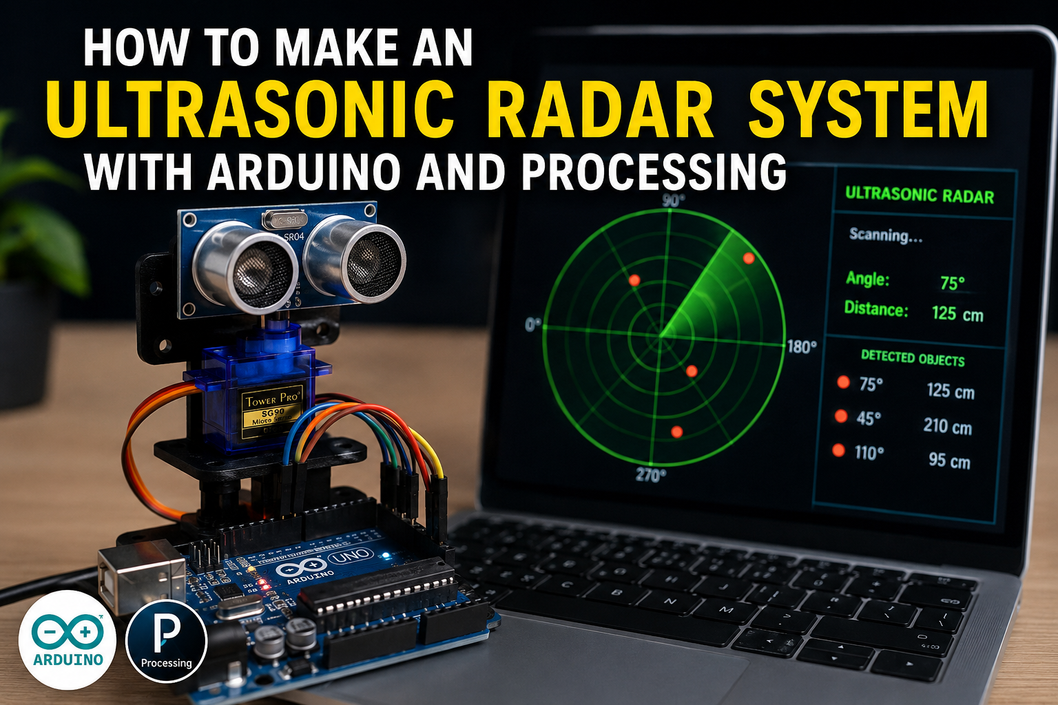
Processing Visualization
The Arduino sends angle and distance data to Processing software running on a computer. Processing converts this data into a radar-style graphical interface.


Bill of Materials (BOM)
| Component | Quantity | Purpose |
|---|---|---|
| Arduino Uno or Nano | 1 | Main controller |
| HC-SR04 Ultrasonic Sensor | 1 | Measures object distance |
| SG90 Servo Motor | 1 | Rotates the sensor |
| Breadboard | 1 | Temporary circuit assembly |
| Jumper Wires | 15+ | Electrical connections |
| USB Cable | 1 | Programming and power |
| Mounting Bracket | 1 | Holds sensor on servo |
| Computer with Processing IDE | 1 | Displays radar visualization |
Estimated Cost
| Item | Approximate Cost (USD) |
|---|---|
| Arduino Uno | $8–15 |
| HC-SR04 Sensor | $2–5 |
| SG90 Servo Motor | $3–6 |
| Miscellaneous Parts | $5–10 |
Total Estimated Cost: $18–36
Circuit Connections Explained
Correct wiring ensures smooth radar operation.
HC-SR04 Connections
- VCC → 5V
- GND → GND
- TRIG → D10
- ECHO → D11
SG90 Servo Motor Connections
- Red Wire → 5V
- Brown/Black Wire → GND
- Orange/Yellow Wire → D9
Tip: If the servo jitters during operation, use an external 5V power source and connect all grounds together.


Step-by-Step Guide: How to Make an Ultrasonic Radar System with Arduino and Processing
Step 1: Install the Arduino IDE
Download and install the Arduino IDE.
Install the required library:
- Servo.h
Step 2: Install Processing Software
Download and install the Processing IDE on your computer.
Processing will be used to create the radar display interface.
Step 3: Assemble the Circuit
Connect the ultrasonic sensor and servo motor according to the wiring table above.
Ensure all connections are secure.
Step 4: Upload the Arduino Code
The Arduino program should:
- Rotate the servo motor.
- Trigger the ultrasonic sensor.
- Calculate object distance.
- Send angle and distance data through the serial port.
Example serial output:
45,35
46,34
47,34
48,33
The first value represents the scanning angle, while the second value indicates the distance in centimeters.
Step 5: Run the Processing Sketch
Open the Processing IDE and upload the visualization code.
The Processing application reads serial data from the Arduino and displays:
- Radar sweep animation
- Object positions
- Distance measurements
- Detection zones
Step 6: Test the Radar System
Place objects at varying distances and observe the radar display.
Verify that:
- The servo rotates smoothly.
- The sensor detects objects accurately.
- The radar interface updates in real time.


Arduino Radar Code Logic
The Arduino program continuously performs the following tasks:
- Rotate the servo from 0° to 180°.
- Send an ultrasonic pulse.
- Measure echo return time.
- Calculate distance using:
Distance = (Time × Speed of Sound) ÷ 2
- Transmit angle and distance values to Processing.
The Processing sketch then converts this data into a visual radar display.
Applications of an Ultrasonic Radar System
This project can be adapted for:
- Obstacle avoidance robots
- Parking assistance systems
- Smart security devices
- Automated doors
- Industrial automation
- Distance monitoring systems
Understanding this project creates a foundation for more advanced robotics and automation systems.
Advantages and Limitations
Advantages
- Affordable components
- Easy to build
- Real-time visualization
- Excellent educational value
- Expandable for robotics projects
Limitations
- Limited detection range
- Performance affected by soft surfaces
- Ultrasonic interference possible
- Not suitable for high-speed tracking
Safety Tips
Follow these precautions during assembly:
- Disconnect power before modifying wiring.
- Secure the sensor firmly to the servo.
- Avoid forcing the servo beyond its rotation limits.
- Keep liquids away from electronics.
Frequently Asked Questions
What Is the Maximum Range of the HC-SR04?
The typical range is 2 cm to 400 cm.
Can I Use an ESP32 Instead of Arduino Uno?
Yes. An ESP32 provides faster processing and wireless connectivity.
Why Is My Radar Display Not Updating?
Verify that:
- The correct serial port is selected.
- Baud rates match in Arduino and Processing.
- The USB cable supports data transfer.
Can This Project Detect Moving Objects?
Yes. The radar display updates continuously and can track moving objects within its range.
How to Fix Common Arduino Upload Errors
Error: “avrdude: stk500_recv(): programmer is not responding”
Solutions:
- Verify the COM port selection.
- Disconnect external modules during upload.
- Replace the USB cable.
- Select the correct board type.
Error: “Board Not Detected”
Solutions:
- Install USB drivers.
- Try another USB port.
- Restart the Arduino IDE.
Error: “Compilation Error: No Such File or Directory”
Solutions:
Install the required library:
- Servo.h
Restart the Arduino IDE after installation.
Error: Processing Cannot Read Serial Data
Solutions:
- Close the Arduino Serial Monitor.
- Confirm the correct COM port.
- Ensure matching baud rates.
Error: Servo Motor Jitters
Solutions:
- Use an external power supply.
- Add a capacitor across the power rails.
- Check loose connections.


Final Thoughts
Learning how to make an ultrasonic radar system with Arduino and Processing is an excellent introduction to robotics, sensor technology, and real-time visualization.
By combining an HC-SR04 ultrasonic sensor, a servo motor, and Processing software, you can build a functional radar system that demonstrates the principles behind object detection and scanning technologies.
Once you master the basic design, you can enhance the project with wireless connectivity, larger displays, and autonomous robotic applications.