Introduction
As the world shifts towards sustainable energy sources, harnessing waste heat for electricity generation presents a valuable opportunity. A thermoelectric generator (TEG) utilizes the Seebeck effect to convert heat into electrical power, making it a promising solution for off-grid power, emergency applications, and energy efficiency improvements.
Abstract
A thermoelectric generator (TEG) is a device that converts heat energy into electrical power using the Seebeck effect. This DIY project demonstrates how to build a simple TEG using thermoelectric modules, a heat source, and a cooling system. The generated electricity can be used to power small devices, charge batteries, or contribute to renewable energy applications.
Statement of the Problem
Many heat sources, such as industrial waste heat, household stoves, and car engines, release unused energy into the environment. Capturing and converting this wasted heat into usable electricity can enhance energy efficiency, reduce reliance on fossil fuels, and provide power in remote or emergency situations. However, thermoelectric power generation is often overlooked due to its perceived complexity and cost. This project aims to simplify the process and make TEGs accessible for DIY enthusiasts.
Objectives
- To construct a working thermoelectric generator using readily available materials.
- To explore the efficiency of TEGs in converting heat into electricity.
- To analyze the factors influencing power output, such as temperature difference and heat dissipation.
- To demonstrate practical applications of TEGs for small-scale energy needs.
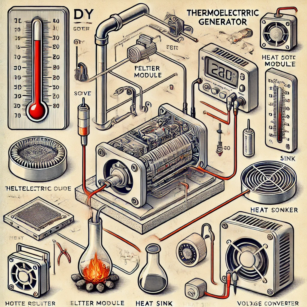
Apparatus/Materials
- Thermoelectric Module (Peltier Module, e.g., TEC1-12706) – Converts heat difference into electricity.
- Heat Source – A small stove, candle, or heated metal plate.
- Heat Sink – Aluminum or copper heat sink to enhance cooling.
- Thermal Grease or Paste – Improves heat transfer efficiency.
- Voltage Regulator (DC-DC Boost Converter, e.g., MT3608) – Stabilizes output voltage.
- Multimeter – To measure output voltage and current.
- Aluminum or Copper Plate – Helps distribute heat evenly.
- Cooling Fan (optional) – Increases temperature difference for better performance.
- Screws and Clamps – To secure components.
- Wires and Soldering Kit – For electrical connections.
Procedure
Step 1: Preparing the Thermoelectric Module
- Identify the hot and cold sides of the thermoelectric module. The labeled side typically faces the cold side.
- Apply thermal grease to both sides of the module to improve heat conduction.
Step 2: Attaching the Heat Sink
- Place the heat sink on the cold side of the thermoelectric module.
- Secure it using screws, clamps, or thermal adhesive.
- If using a cooling fan, attach it to the heat sink for improved cooling.
Step 3: Positioning the Heat Source
- Place the hot side of the thermoelectric module on a heat-conductive surface (e.g., aluminum plate or stove surface).
- Ensure the setup is stable and can withstand high temperatures.
- Gradually increase the heat to avoid thermal shock.
Step 4: Connecting the Electrical Components
- Connect the positive (red) and negative (black) wires from the thermoelectric module to the voltage regulator input.
- Adjust the boost converter to maintain a stable voltage output (e.g., 5V or 12V depending on application).
- Use a multimeter to measure the generated voltage and current.
Step 5: Data Collection
- Measure the initial temperature of the hot and cold sides before applying heat.
- Record the voltage and current output at different temperature differences.
- Test with and without additional cooling mechanisms (such as a fan or larger heat sink).
- Observe how output varies when multiple thermoelectric modules are connected in series or parallel.
Discussion of Results
The output voltage and current were found to increase with a greater temperature difference between the hot and cold sides. The use of a larger heat sink and active cooling improved efficiency by maintaining a more significant temperature differential.
- Voltage Output: The highest recorded voltage was achieved when the temperature difference exceeded 80°C.
- Current Output: Higher efficiency was noted when multiple TEGs were connected in parallel.
- Limitations: The power output was limited due to the inherent inefficiency of Peltier modules, which are primarily designed for cooling rather than power generation.
Conclusion
This DIY thermoelectric generator project successfully demonstrated how waste heat can be converted into electricity using a thermoelectric module, a heat sink, and a heat source. The generated electricity can be used for small-scale applications, such as charging devices or running low-power electronics. While efficiency remains a challenge, optimization through better cooling and multiple modules can improve performance.
Recommendations
- Use high-efficiency thermoelectric modules designed specifically for power generation.
- Implement better cooling mechanisms, such as water-cooled heat sinks.
- Combine multiple TEG modules to increase total power output.
- Explore applications like charging small batteries or integrating with solar power systems for hybrid energy solutions.