Introduction
Light data transfer, often referred to as “optical communication,” involves transmitting data through light signals rather than traditional electronic signals. This technology forms the backbone of many modern communication systems, including fiber-optic networks. Optical communication is known for its high speed, reliability, and ability to transfer large amounts of data over long distances with minimal signal degradation. This project explores the basics of light data transfer, its applications, and a simple experiment demonstrating how data can be transmitted using light.
Abstract
This project demonstrates the principles of light data transfer by using a basic setup to send data through a beam of light. By utilizing components such as LEDs, photodiodes, and an oscilloscope, this experiment models how data transmission works in fiber-optic and other optical communication systems. The project outlines the materials needed, the procedure for setting up the system, and observations on how light can effectively transmit data. This guide is ideal for students and hobbyists interested in learning the fundamentals of optical communication.
Materials
To successfully complete this light data transfer project, you will need the following materials:
- LED (Light Emitting Diode): Serves as the light source to transmit data.
- Photodiode or Phototransistor: Acts as the receiver to detect light signals.
- Microcontroller or Oscilloscope: For generating and reading data signals.
- Resistors: Used to control the current flowing through the circuit.
- Wires and Breadboard: For assembling the circuit.
- Battery or Power Source: Powers the LED and microcontroller.
- Optical Fiber (Optional): To demonstrate light-guided data transmission over a distance.
- Multimeter (Optional): To measure voltages and ensure proper circuit functioning.
Procedure
Step 1: Setup the LED Transmitter
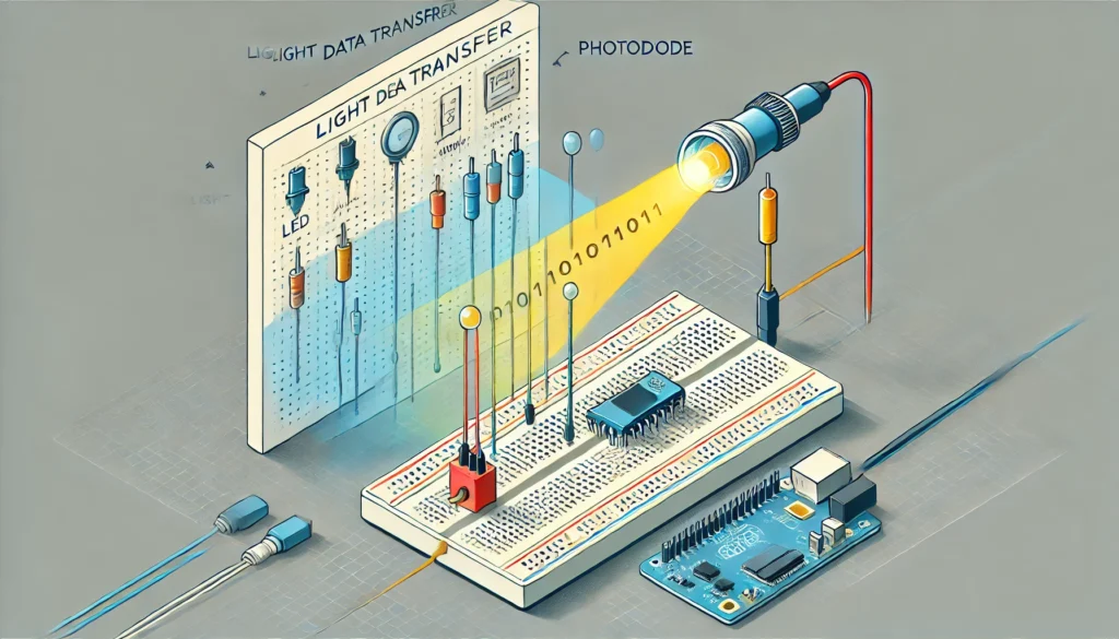
- Prepare the Circuit: Connect the LED to a power source with a resistor to limit the current. This LED will act as the transmitter, sending out light pulses that carry data.
- Data Encoding: Use a microcontroller or function generator to create a binary signal (ones and zeros) that will modulate the LED. For example, turning the LED on can represent a “1,” and turning it off can represent a “0.”
- Program the Signal: Program the microcontroller to send a series of on and off signals to the LED. This sequence of light pulses represents the data being transmitted.
Step 2: Set up the Photodiode Receiver
- Install the Photodiode: Connect the photodiode in a simple circuit that includes a resistor and connects to the oscilloscope or microcontroller input.
- Align with LED: Position the photodiode facing the LED so it can effectively detect the light signals emitted. Ensure there are no obstructions between the LED and photodiode, as this could interfere with data transfer.
- Signal Conditioning: If necessary, use an amplifier circuit to boost the signal from the photodiode so it can be more easily detected by the oscilloscope or microcontroller.
Step 3: Transmit the Data
- Power the LED and Photodiode: Turn on the power source and ensure both the LED and photodiode circuits are functioning properly.
- Begin Transmission: Send the data signal through the LED. The light pulses should be picked up by the photodiode, which will convert them back into electrical signals.
- Monitor the Signal: Observe the output of the photodiode on an oscilloscope or microcontroller. You should see a waveform that matches the on and off pulses sent by the LED, indicating successful data transmission.
Step 4: Analyze Data Transmission
- Check for Signal Consistency: Compare the transmitted and received signals to confirm accuracy. Any deviation could indicate interference or signal loss.
- Repeat with Adjustments: Adjust the distance between the LED and photodiode to test the limits of the transmission range. Optionally, insert an optical fiber between them to simulate a fiber-optic cable setup and observe the impact on data fidelity.
Results
The results of this experiment should demonstrate successful data transfer through light. If the setup is correct, the photodiode will accurately detect the on and off pulses from the LED, resulting in a signal that matches the original data. This process mimics how fiber-optic systems transmit data using light, albeit on a smaller and simpler scale. You’ll observe that as the distance increases, the signal strength may weaken, showcasing the need for guided channels, such as optical fibers, for long-distance data transmission.
Conclusion
This project provides a practical insight into how light can be used to transmit data, laying the groundwork for understanding fiber-optic communication systems. Light data transfer is highly efficient, allowing for rapid transmission of information with minimal loss. Through this experiment, you gain hands-on experience in setting up a basic optical communication system, from encoding data into light pulses to decoding it at the receiver.
The experiment also highlights some key considerations in optical communication, such as alignment, signal loss over distance, and the need for amplification. With advancements in fiber optics and laser technology, light-based data transfer continues to be a cornerstone of modern communication networks, facilitating high-speed internet, telecommunication, and data centers worldwide.
This project not only emphasizes the fundamentals of data transfer using light but also encourages further exploration into advanced topics such as fiber optics, laser communication, and photonics, opening doors to deeper understanding and innovation in the field of optical communication.


I just could not go away your web site prior to suggesting that I extremely loved the standard info a person provide for your guests? Is gonna be again steadily in order to investigate cross-check new posts
I have realized some new items from your website about pcs. Another thing I have always thought is that computers have become a specific thing that each house must have for several reasons. They supply you with convenient ways in which to organize homes, pay bills, go shopping, study, focus on music and perhaps watch tv shows. An innovative approach to complete many of these tasks is by using a laptop computer. These desktops are mobile, small, powerful and convenient.